
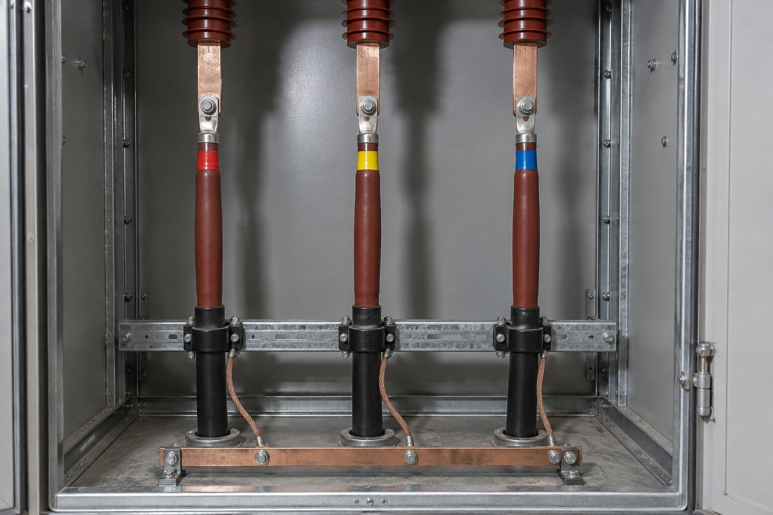
- Most delays come from the cables, not the unit: length, condition and the right termination kit.
- The ring lets the operator re-feed customers from the other side, so the outage plan is a switching plan first.
- Carry spare termination and joint kits to site. A cable that fails its test must not extend the outage by a day.
- Nothing is energised until insulation, functional, protection and phasing checks are recorded.
When an RMU is replaced
A ring main unit (RMU) sits on a medium-voltage ring and lets the network operator switch either side of the ring and feed a transformer or a customer. Units are replaced when gas pressure can no longer be held, when a mechanism or bushing has failed, after a flashover, or when the model is obsolete and can no longer be supported.
The survey before the outage
A replacement is prepared on the existing unit while it is still live, without opening anything. The survey records:
- The configuration, for example three ring switches and one circuit-breaker feeder, and whether the new unit matches it
- The footprint, fixing points and cable entry positions of the old and new units
- Each cable's size and type, for example three-core 240 mm², and whether it has enough length to reach the new bushings
- The termination type the new unit needs, usually separable elbow connectors matched to the cable
- The condition of the plinth, trench and earthing
- Protection relay settings and current-transformer ratios to be carried over
The outage plan
Because the unit is on a ring, the operator can open the ring at this point and keep feeding the other substations from both ends. The customers fed directly from the unit being replaced lose supply for the duration, so the plan is agreed with the operator and those customers in advance.
The plan sets out the switching sequence, the permit to work, the points of isolation and earthing, the work steps with a time for each, and the contingencies. The most useful contingency is material on site: spare termination kits, and joint kits in case a cable is too short or has to be cut back.
The work on the day
- Isolate, prove dead and earth every cable under the permit
- Label each cable and phase before disconnecting
- Remove the old unit; set, level and fix the new unit and connect its earthing
- Prepare the cables and make the new terminations to the kit instructions
- Test, then hand back to the operator for energisation in sequence
Tests before energising
- Insulation resistance of each cable and of the unit
- Cable tests the owner requires, such as sheath and withstand tests
- Functional operation of every switch, earth switch and interlock
- Gas pressure indication
- Protection relay testing by injection, with current-transformer ratio and polarity checks
- Phasing check across the open point before the ring is closed
The results go into the handover file together with the as-built single-line diagram and the relay settings applied.
Inspecting the units you are not replacing
A replacement is a good time to inspect the neighbouring units on the same ring: gas pressure, indicators, mechanism operation, relay settings against the approved values, and cable test results. A unit found weak during a planned visit is far cheaper than one that fails in service.
Where ETC fits
ETC replaces and inspects ring main units up to 33 kV, including elbow terminations, cable testing and primary-injection testing of protection, and works under the network operator's switching and permit procedures.